STM32を使って作りたいのはGPSロガーです。パーツとしておそらく以下のようなものを使うはず。
- デジタル出力
- 電源の制御
- LEDの点灯状態の制御
- デジタル入力
- タクトスイッチの押下状態の取得
- アナログ入力
- 電源電圧の監視
- SPI
- SDカードへのNMEAの書き込み
- マイコンの省電力制御
- EXTI割り込み
- タクトスイッチ押下により、省電力状態からの復帰
- USARTによる受信
- GPSからのNMEA情報の受信
今のところ、3.までこなしました。続いて4.の通り、SPIを使用してSDカードへのアクセスを試します。
ところで・・・
無知とは恐ろしいです。
ARMマイコンでGPSロガーを作りたいな→8ビットマイコンの置き換えも狙っているCortex-M0マイコンで作ってみよう→NXPは使いにくそうだし(イメージ先行)STM32にしよう→STM32F0もいいけど、より省電力が期待できるSTM32L0にしよう。みたいな流れです。Arduino(あるいはAVRマイコン)のありがたいところは有志によるライブラリが沢山あり、ハードを動かすソフトウェアを一から作ることはほとんどないところにあります。しかし、STM32はそうはいかないようで、SDカードのアクセスの場合もちょっとだけ苦労しました。
同じSTM32マイコンでもF1やF4シリーズだと有志による実装をすぐに見つけることができたのですが、L0はそうはいきませんでした。STM32CubeMXではFatFsの選択ができるのに…ハードに近い部分の処理は開発者が実装しなければならない状態です。ウムム・・・
でも、気を取り直して STM32CubeL0 Embedded software for STM32L0 series (HAL low level drivers, USB, File system, RTOS, Touch Sensing – coming with examples running on ST boards: STM32 Nucleo, Discovery kits and Evaluation boards) – STMicroelectronics からSTM32Cubeをダウンロードしその内容確認したところ、使えそうなソースがありました。

STM32Cube_FW_L0_V1.4.0/Drivers/BSP/Adafruit_Shield に stm32_adafruit_sd.c と stm32_adafruit_sd.h があり、ハードを使いこなす処理をSDカードアクセス処理のレベルで抽象化したAPIを呼び出しています。その呼び出されるAPIを実装しており、使いやすそうなソースが STM32Cube_FW_L0_V1.4.0/Drivers/BSP/STM32L0xx_Nucleo に stm32l0xx_nucleo.c と stm32l0xx_nucleo.h がありました。また、 STM32Cube_FW_L0_V1.4.0/Middlewares/Third_Party/FatFs/src/drivers に sd_diskio.c と sd_diskio.h があり、 stm32_adafruit_sd.c/h 提供のAPIを呼び出しており、FatFs本体とを つなぐ ようになっていました。
つまり、以下のような呼び出し関係になってそうです。
アプリ
  ↓
FatFs本体
  ↓
sd_diskio.c/h(FatFs Moduleの一部)
  ↓
stm32_adafruit_sd.c/h
  ↓
stm32l0xx_nucleo.c/h
  ↓
HALライブラリ
sd_diskio.c/h はほとんどそのまま使用できそうであり、stm32_adafruit_sd.c/h、stm32l0xx_nucleo.c/h はSDカードアクセスに必要な部分のみ使用し、他(JoyStick, LCD, LED)に関するソースを無効化することで動かせそうです。(実際動き、ファイルの作成・書き込みと読み込みができました)
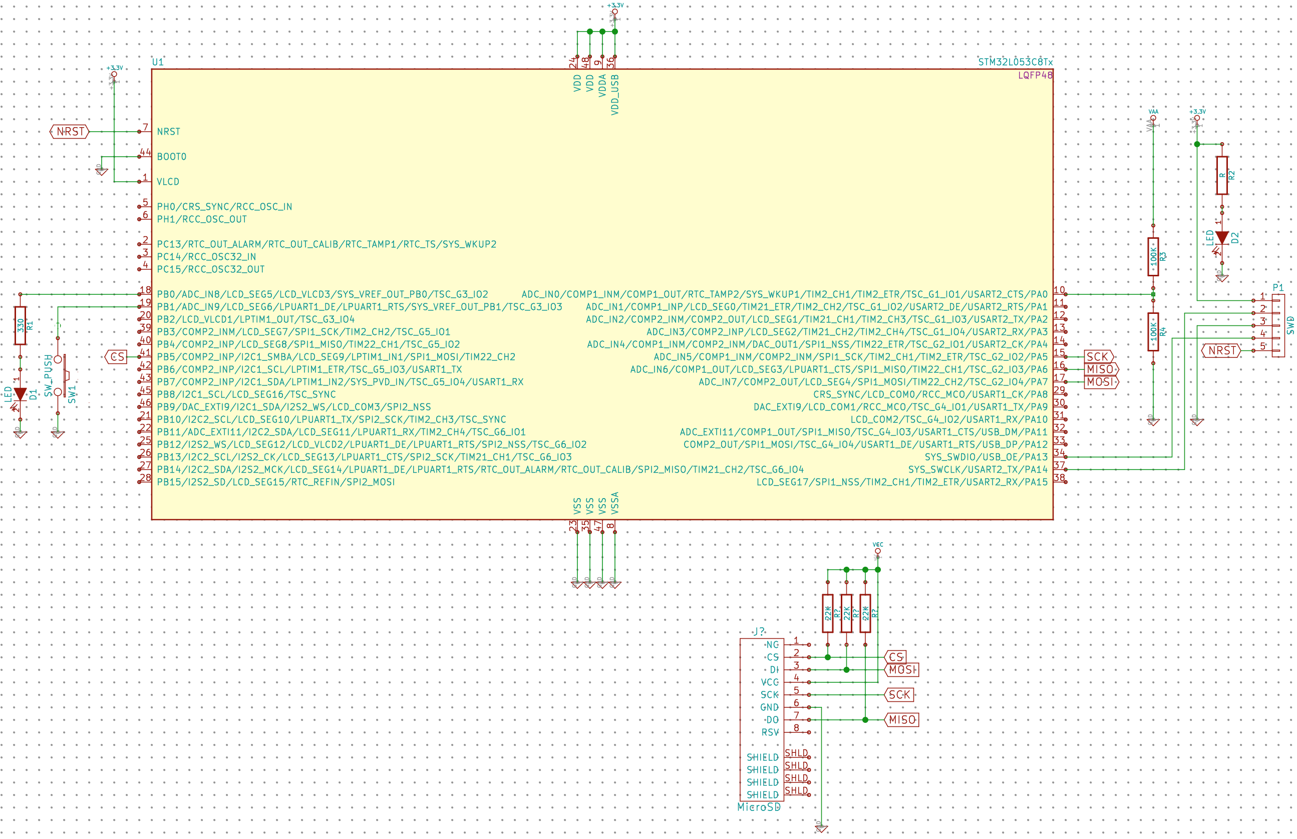
回路図
SDカードをSPIによりアクセスするため、SPI1にSDカードを接続します。また、CSの制御のためGPIOを使用します。

STM32CubeMX
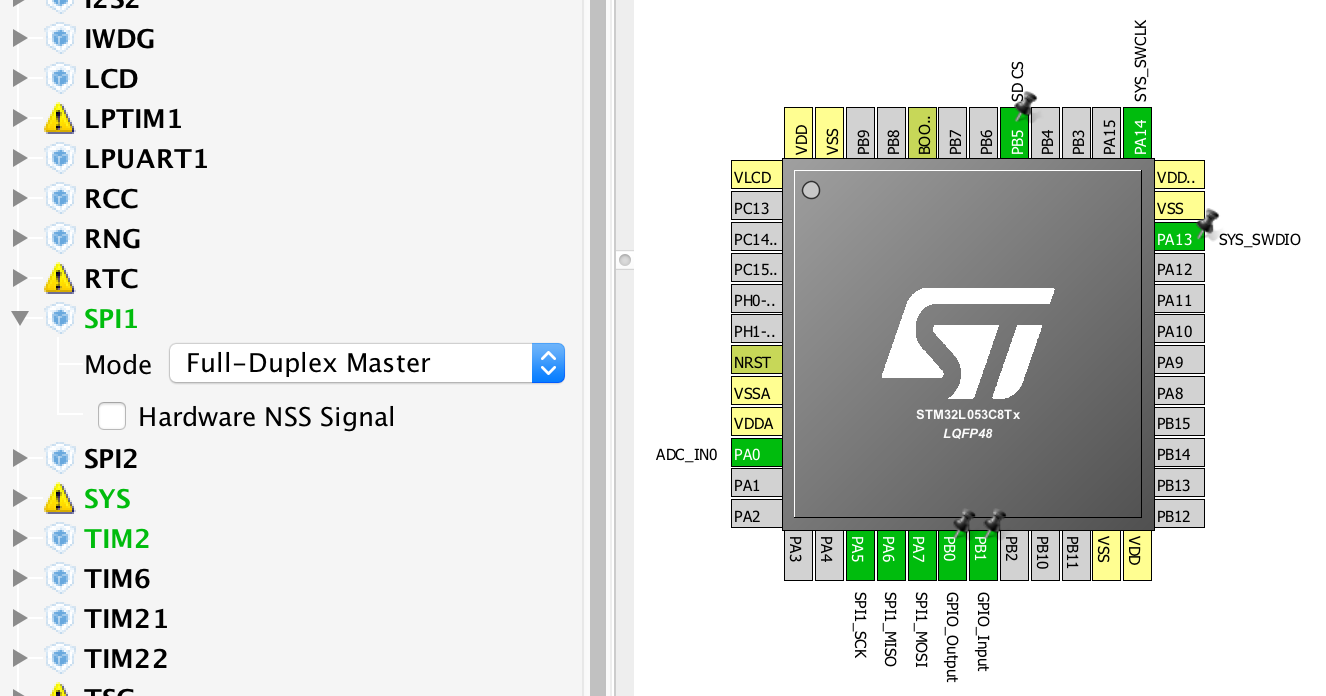
これまで作成したSTM32CubeMXプロジェクトにSPIを追加します。またCS信号のため、GPIOを一つ割り当てます。SPIやGPIOの初期化コードは上記ソースに含まれており、STM32CubeMXで設定する必要は本来ないのですが、stm32l0xx_nucleo.c/h に #ifdef HAL_SPI_MODULE_ENABLED 〜 #endif というコードがあり、これによりSTM32CubeMXで設定していなければ必要な処理が無効化されます。includeファイル内で定義する、もしくは #ifdef HAL_SPI_MODULE_ENABLED 、 #endif を削除することも考えられますが、一旦STM32CubeMXにて使用を宣言します。

Peripherals >> SPI1 を開き、 Mode を Full-Duplex Master に設定します。
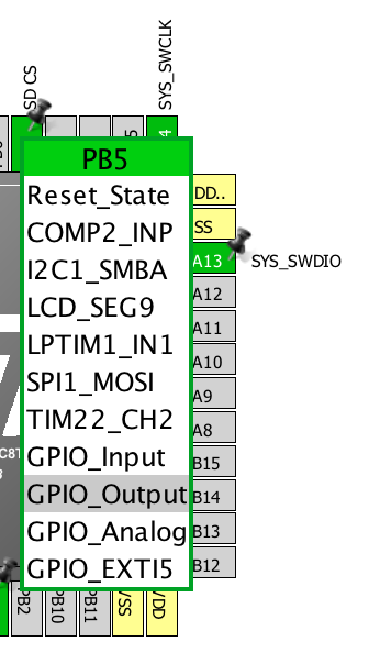
また、 PB5 を GPIO_Output に設定します。

SPIについて、BSP側のソースで設定しているため、これ以上の設定は行いません(GPSロガーを作るまでにこのやり方はやめるつもり)。
コードを生成し、以降Eclipse本体で作業を行います。
- sd_diskio.c/h
- stm32_adafruit_sd.c/h
- stm32l0xx_nucleo.c/h
上記ソースをEclipseプロジェクトの適当な場所に格納します。
- SW4STM32/L0SampleFatFs Configuration/Application/User/BSP
- stm32_adafruit_sd.c
- stm32_adafruit_sd.h
- stm32l0xx_nucleo.c
- stm32l0xx_nucleo.h
- SW4STM32/L0SampleFatFs Configuration/Application/User/fatfs
- sd_diskio.c
- sd_diskio.h
当方では、上記の通り配置しました。
次にSDカード以外の処理を削除していきます。どれを削除すれば良いかは分かりやすいと思います。定義名の接頭辞や途中にが SD_ がついている定義や関数を残し、他を削除すれば良いのです。
diff --git a/SW4STM32/L0SampleFatFs Configuration/Application/User/fatfs/sd_diskio.c b/SW4STM32/L0SampleFatFs Configuration/Appl ication/User/fatfs/sd_diskio.c old mode 100755 new mode 100644 index cb16735..d798cf5 --- a/SW4STM32/L0SampleFatFs Configuration/Application/User/fatfs/sd_diskio.c +++ b/SW4STM32/L0SampleFatFs Configuration/Application/User/fatfs/sd_diskio.c @@ -28,6 +28,9 @@ /* Includes ------------------------------------------------------------------*/ #include#include "ff_gen_drv.h" +#ifndef USE_NUCLEO +#include "../BSP/stm32_adafruit_sd.h" +#endif /* USE_NUCLEO */ /* Private typedef -----------------------------------------------------------*/ /* Private define ------------------------------------------------------------*/ @@ -49,7 +52,11 @@ DRESULT SD_read (BYTE, BYTE*, DWORD, UINT); DRESULT SD_ioctl (BYTE, BYTE, void*); #endif /* _USE_IOCTL == 1 */ +#ifdef USE_NUCLEO const Diskio_drvTypeDef SD_Driver = +#else /* USE_NUCLEO */ +const Diskio_drvTypeDef USER_Driver = +#endif /* USE_NUCLEO */ { SD_initialize, SD_status,
diff --git a/SW4STM32/L0SampleFatFs Configuration/Application/User/BSP/stm32l0xx_nucleo.c b/SW4STM32/L0SampleFatFs Configuration
/Application/User/BSP/stm32l0xx_nucleo.c
index 3420c82..71ea981 100755
--- a/SW4STM32/L0SampleFatFs Configuration/Application/User/BSP/stm32l0xx_nucleo.c
+++ b/SW4STM32/L0SampleFatFs Configuration/Application/User/BSP/stm32l0xx_nucleo.c
@@ -101,12 +101,14 @@
 /** @defgroup STM32L0XX_NUCLEO_LOW_LEVEL_Private_Variables
   * @{
   */
+#ifdef USE_NUCLEO
 GPIO_TypeDef* LED_PORT[LEDn] = {LED2_GPIO_PORT};
 const uint16_t LED_PIN[LEDn] = {LED2_PIN};

 GPIO_TypeDef* BUTTON_PORT[BUTTONn] = {KEY_BUTTON_GPIO_PORT };
 const uint16_t BUTTON_PIN[BUTTONn] = {KEY_BUTTON_PIN };
 const uint8_t BUTTON_IRQn[BUTTONn] = {KEY_BUTTON_EXTI_IRQn };
+#endif // USE_NUCLEO

 /**
  * @brief BUS variables
@@ -118,9 +120,11 @@ static SPI_HandleTypeDef hnucleo_Spi;
 #endif /* HAL_SPI_MODULE_ENABLED */

 #ifdef HAL_ADC_MODULE_ENABLED
+#ifdef USE_NUCLEO
 static ADC_HandleTypeDef hnucleo_Adc;
 /* ADC channel configuration structure declaration */
 static ADC_ChannelConfTypeDef sConfig;
+#endif // USE_NUCLEO
 #endif /* HAL_ADC_MODULE_ENABLED */
 /**
   * @}
@@ -142,16 +146,20 @@ void                      SD_IO_WriteReadData(const uint8_t *DataIn, uint8_t *Da
 uint8_t                   SD_IO_WriteByte(uint8_t Data);

 /* LCD IO functions */
+#ifdef USE_NUCLEO
 void                      LCD_IO_Init(void);
 void                      LCD_IO_WriteData(uint8_t Data);
 void                      LCD_IO_WriteMultipleData(uint8_t *pData, uint32_t Size);
 void                      LCD_IO_WriteReg(uint8_t LCDReg);
 void                      LCD_Delay(uint32_t delay);
+#endif // USE_NUCLEO
 #endif /* HAL_SPI_MODULE_ENABLED */

 #ifdef HAL_ADC_MODULE_ENABLED
+#ifdef USE_NUCLEO
 static void               ADCx_Init(void);
 static void               ADCx_MspInit(ADC_HandleTypeDef *hadc);
+#endif // USE_NUCLEO
 #endif /* HAL_ADC_MODULE_ENABLED */
 /**
   * @}
@@ -171,6 +179,7 @@ uint32_t BSP_GetVersion(void)
   return __STM32L0XX_NUCLEO_BSP_VERSION;
 }

+#ifdef USE_NUCLEO
 /**
   * @brief  Configures LED GPIO.
   * @param  Led: Specifies the Led to be configured.
@@ -284,6 +293,7 @@ uint32_t BSP_PB_GetState(Button_TypeDef Button)
 {
   return HAL_GPIO_ReadPin(BUTTON_PORT[Button], BUTTON_PIN[Button]);
 }
+#endif // USE_NUCLEO


 #ifdef HAL_SPI_MODULE_ENABLED
@@ -444,12 +454,14 @@ void SD_IO_Init(void)


   /* Configure LCD_CS_PIN pin: LCD Card CS pin */
+#ifdef USE_NUCLEO
   GPIO_InitStruct.Pin = LCD_CS_PIN;
   GPIO_InitStruct.Mode = GPIO_MODE_OUTPUT_PP;
   GPIO_InitStruct.Pull = GPIO_NOPULL;
   GPIO_InitStruct.Speed = GPIO_SPEED_FREQ_VERY_HIGH;
   HAL_GPIO_Init(SD_CS_GPIO_PORT, &GPIO_InitStruct);
   LCD_CS_HIGH();
+#endif // USE_NUCLEO

   /*------------Put SD in SPI mode--------------*/
   /* SD SPI Config */
@@ -507,6 +519,7 @@ uint8_t SD_IO_WriteByte(uint8_t Data)
 }

 /********************************* LINK LCD ***********************************/
+#ifdef USE_NUCLEO
 /**
   * @brief  Initializes the LCD
   * @param  None
@@ -645,10 +658,12 @@ void LCD_Delay(uint32_t Delay)
 {
   HAL_Delay(Delay);
 }
+#endif // USE_NUCLEO
 #endif /* HAL_SPI_MODULE_ENABLED */

 /******************************* LINK JOYSTICK ********************************/
 #ifdef HAL_ADC_MODULE_ENABLED
+#ifdef USE_NUCLEO
 /**
   * @brief  Initializes ADC MSP.
   * @param  None
@@ -789,6 +804,7 @@ JOYState_TypeDef BSP_JOY_GetState(void)
   /* Return the code of the Joystick key pressed */
   return state;
 }
+#endif // USE_NUCLEO
 #endif /* HAL_ADC_MODULE_ENABLED */

 /**
diff --git a/SW4STM32/L0SampleFatFs Configuration/Application/User/BSP/stm32l0xx_nucleo.h b/SW4STM32/L0SampleFatFs Configuration
/Application/User/BSP/stm32l0xx_nucleo.h
index 20912f3..5021c1a 100755
--- a/SW4STM32/L0SampleFatFs Configuration/Application/User/BSP/stm32l0xx_nucleo.h
+++ b/SW4STM32/L0SampleFatFs Configuration/Application/User/BSP/stm32l0xx_nucleo.h
@@ -66,6 +66,7 @@
 /** @defgroup STM32L0XX_NUCLEO_LOW_LEVEL_Exported_Types
   * @{
   */
+#ifdef USE_NUCLEO
 typedef enum
 {
   LED2 = 0,
@@ -94,6 +95,7 @@ typedef enum
   JOY_RIGHT = 4,
   JOY_UP    = 5
 } JOYState_TypeDef;
+#endif // USE_NUCLEO

 /**
   * @}
@@ -113,6 +115,7 @@ typedef enum
 /** @addtogroup STM32L0XX_NUCLEO_LOW_LEVEL_LED
   * @{
   */
+#ifdef USE_NUCLEO
 #define LEDn                               1

 #define LED2_PIN                           GPIO_PIN_5
@@ -122,6 +125,7 @@ typedef enum

 #define LEDx_GPIO_CLK_ENABLE(__INDEX__)    do {LED2_GPIO_CLK_ENABLE(); } while(0)
 #define LEDx_GPIO_CLK_DISABLE(__INDEX__)   LED2_GPIO_CLK_DISABLE())
+#endif // USE_NUCLEO
 /**
   * @}
   */
@@ -129,6 +133,7 @@ typedef enum
 /** @addtogroup STM32L0XX_NUCLEO_LOW_LEVEL_BUTTON
   * @{
   */
+#ifdef USE_NUCLEO
 #define BUTTONn                            1

 /**
@@ -150,6 +155,7 @@ typedef enum

 #define BUTTONx_GPIO_CLK_ENABLE(__INDEX__)     do {KEY_BUTTON_GPIO_CLK_ENABLE(); } while(0)
 #define BUTTONx_GPIO_CLK_DISABLE(__INDEX__)    (KEY_BUTTON__GPIO_CLK_DISABLE())
+#endif // USE_NUCLEO
 /**
   * @}
   */
@@ -198,10 +204,12 @@ typedef enum
 /**
   * @brief  LCD Control Lines management
   */
+#ifdef USE_NUCLEO
 #define LCD_CS_LOW()      HAL_GPIO_WritePin(LCD_CS_GPIO_PORT, LCD_CS_PIN, GPIO_PIN_RESET)
 #define LCD_CS_HIGH()     HAL_GPIO_WritePin(LCD_CS_GPIO_PORT, LCD_CS_PIN, GPIO_PIN_SET)
 #define LCD_DC_LOW()      HAL_GPIO_WritePin(LCD_DC_GPIO_PORT, LCD_DC_PIN, GPIO_PIN_RESET)
 #define LCD_DC_HIGH()     HAL_GPIO_WritePin(LCD_DC_GPIO_PORT, LCD_DC_PIN, GPIO_PIN_SET)
+#endif // USE_NUCLEO

 /**
   * @brief  SD Control Interface pins
@@ -211,6 +219,7 @@ typedef enum
 #define SD_CS_GPIO_CLK_ENABLE()                 __HAL_RCC_GPIOB_CLK_ENABLE()
 #define SD_CS_GPIO_CLK_DISABLE()                __HAL_RCC_GPIOB_CLK_DISABLE()

+#ifdef USE_NUCLEO
 /**
   * @brief  LCD Control Interface pins
   */
@@ -242,6 +251,7 @@ typedef enum
 #define NUCLEO_ADCx_GPIO_CLK_DISABLE()            __HAL_RCC_GPIOB_CLK_ENABLE()

 #endif /* HAL_ADC_MODULE_ENABLED */
+#endif // USE_NUCLEO

 /**
   * @}
@@ -259,6 +269,7 @@ typedef enum
   * @{
   */
 uint32_t         BSP_GetVersion(void);
+#ifdef USE_NUCLEO
 void             BSP_LED_Init(Led_TypeDef Led);
 void             BSP_LED_On(Led_TypeDef Led);
 void             BSP_LED_Off(Led_TypeDef Led);
@@ -269,6 +280,7 @@ uint32_t         BSP_PB_GetState(Button_TypeDef Button);
 uint8_t          BSP_JOY_Init(void);
 JOYState_TypeDef BSP_JOY_GetState(void);
 #endif /* HAL_ADC_MODULE_ENABLED */
+#endif // USE_NUCLEO
 /**
   * @}
   */
見ての通り、#ifdef USE_NUCLEO〜#endif で括っています。 USE_NUCLEOは定義していないので、結果として括られた部分の処理は無効となります。
/Src/fatfs.c にSDカードのマウント処理を追加します。また、semihostingを使用しているので、 initialise_monitor_handles(); も追加しています。
/* USER CODE BEGIN Variables */
extern void initialise_monitor_handles(void);
FATFS SDFatFs;  /* File system object for SD card logical drive */
/* USER CODE END Variables */
  :
void MX_FATFS_Init(void)
{
  /*## FatFS: Link the USER driver ###########################*/
  retUSER = FATFS_LinkDriver(&USER_Driver, USER_Path);

  /* USER CODE BEGIN Init */
  FRESULT res;
  initialise_monitor_handles();
  res = f_mount(&SDFatFs, (TCHAR const*)USER_Path, 0);
  printf("f_mount() res=%d\n", (int)res);
  /* USER CODE END Init */
}
main()関数にサンプルとしてファイルの書き込みを行い、その内容を読み出すソースを記述します。
int main(void)
{

  /* USER CODE BEGIN 1 */
  uint32_t byteswritten, bytesread;                     /* File write/read counts */
  FIL MyFile;     /* File object */
  uint8_t wtext[] = "This is STM32 working with FatFs"; /* File write buffer */
  uint8_t rtext[100];                                   /* File read buffer */
  FRESULT res;                                          /* FatFs function common result code */
  /* USER CODE END 1 */
    :
  /* USER CODE BEGIN 2 */
  res = f_open(&MyFile, "STM32.TXT", FA_CREATE_ALWAYS | FA_WRITE);
  printf("f_open() res=%d\n", (int)res);
  if (res == FR_OK) {
    res = f_write(&MyFile, wtext, sizeof(wtext), (void *)&byteswritten);
    printf("f_write() res=%d, byteswritten=%lu\n", (int)res, byteswritten);
    f_close(&MyFile);
  }

  res = f_open(&MyFile, "STM32.TXT", FA_READ);
  printf("open() res=%d\n", (int)res);
  if (res == FR_OK) {
    res = f_read(&MyFile, rtext, sizeof(rtext), (UINT*)&bytesread);
    printf("f_read() res=%d, bytesread=%lu, rtext=%s\n", (int)res, byteswritten, rtext);
    f_close(&MyFile);
  }
  FATFS_UnLinkDriver(USER_Path);
  /* USER CODE END 2 */

  while (1);
}
Open On-Chip Debugger 0.9.0 (2015-05-28-12:05)
Licensed under GNU GPL v2
For bug reports, read
    http://openocd.org/doc/doxygen/bugs.html
Info : FTDI SWD mode enabled
adapter speed: 300 kHz
adapter_nsrst_delay: 100
  :
semihosting is enabled
f_mount() res=0
f_open() res=0
f_write() res=0, byteswritten=33
open() res=0
f_read() res=0, bytesread=33, rtext=This is STM32 working with FatFs